

AFTER-SALES SERVICE
Usage Instructions
1. Design and installation considerations
When selecting an installation site, please pay attention to the following considerations:
● Please install in a well-ventilated and clean location.
● Please avoid places with a lot of dust and acidic gas emissions.
● Please avoid locations with chimneys and other heat source machines to prevent the influence of exhaust heat and radiant heat.
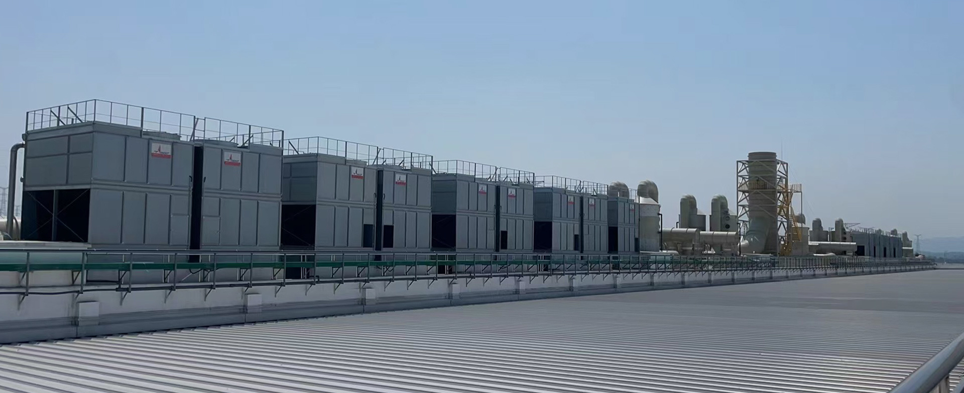
● Please place the tower body horizontally and securely fix the foundation with fixing bolts.
● Since air is drawn in from all sides through the louver, please refer to the product specifications for the distance between the cooling tower and other obstacles such as walls. If the amount of air drawn in is lower than the design value, it will lead to insufficient heat dissipation capacity.
● Please be careful not to allow the air discharged from the cooling tower to be drawn back into the tower after circulation, causing a short circuit.
● In cases where the height of the outer wall is higher than that of the tower body, it is recommended to install right-angle piping. In cases easily affected by external winds, it is recommended to install right-angle piping or bent pipes as countermeasures. The height of obstacles should be the same as or lower than the height of the fan. Otherwise, if the obstacle is higher than the fan, it is easy to cause airflow short circuits.
When designing piping and surroundings, please pay attention to the following considerations:
● Please confirm the direction of the inlet and outlet piping marked on the drawings.
● Please confirm the position of the anti-vibration frame and foundation holes.
● When designing the circulating water piping, please ensure that the resistance of the piping is not designed to be too large, and do not design the vertical movement range of the piping to be too large.
● In cases where the tower has internal piping with regulating valves, please install valves on the inlet pipe of the cooling tower to adjust the water supply to each water tank.
● Ensure that the sewage pipe and sewage valve are installed at the outlet of the water system pump for easy sewage discharge.
● Please use piping with a diameter larger than the interface pipe diameter.
● Please install a filter screen in the circulating piping outside the cooling tower, near the piping outlet.
● When selecting a circulating water pump, please choose appropriately.
● Please be careful not to make the length of the drainage pipe connection too long, and please use a larger diameter pipe.
● When installing a frost-proof electric heater in the lower water tank, it is recommended to use a water level alarm.
● Please install an expansion water tank between the cooling tower's circulating water pipe and the water pump, and it should be installed at the top of the cooling tower. Since the circulating water system piping is a closed loop, an expansion water tank is necessary to absorb water. It is necessary to supplement the water that drips from the pressure cover seal of the circulating water pump.
● During winter operation, please install a frost-proof electric heater in the lower water tank (for the watering system), a frost-proof electric heater for the circulating water system, and an auxiliary water pump to prevent the circulating water from freezing, assisting in the operation of the circulating water in the cooling tower. For detailed information, please consult our company.
2. Precautions for storing equipment before installation
When storing equipment before installation, do not cover the unit with an oil cloth or other coverings, as covering the unit may cause overheating and damage the PVC water baffle and cooling tower fill. During long-term storage, regularly rotate the fan and fan shaft, and lubricate all bearings. During trial operation, clean the bearings and add new grease.
3. Precautions for setting up steel structure foundations
For units with a width B greater than 7.3 meters, it is required to use three sufficiently long I-beams as the base, which are used to fix the lower surface of the unit's outer bottom flange. The bottom flange of the unit has installation holes with a diameter of 19mm for fastening bolts to the I-beams (see the precise location of the bolt holes provided in the official drawings).
The size of the I-beam should be determined based on engineering experience, with the maximum deflection of the I-beam being 1/360 of the unit length and not exceeding 13mm. The deflection of the I-beam can also be calculated based on 55% of the operating weight with a uniformly distributed load (see drawings for operating weight). The I-beam must be leveled before placing the unit on it; shims should not be used between the water tray flange and the I-beam to find level, otherwise, good longitudinal support cannot be achieved. The I-beam and anchor bolts are provided by other manufacturers; the weight, size, and technical data of the unit can be found in the unit's outline drawing.


Focus on us

Tyacht Cooling Technology

Tyacht Scholarship

©2024 Shanghai Tyacht Cooling System Co.,Ltd Powered by: CEglobal SEO Privacy Policy